We seek to understand and document all radio transmissions, legal and otherwise, as part of the radio listening hobby. We do not encourage any radio operations contrary to regulations. Always consult with the appropriate authorities if you have questions concerning what is permissible in your locale.

Show Posts

This section allows you to view all posts made by this member. Note that you can only see posts made in areas you currently have access to.


Messages - Radiotech

Pages: [1] 2
1
The RF Workbench / Re: Hellschreiber Beacon Mk II
« on: July 03, 2022, 2019 UTC »
You are probably right streachyman, my designs will never become very usefull or efficient, designing things my self(without propper expertise) and soldering together old parts is probably a waste of time.  :) It is summer time so i will throw out this old project and spend some time in the sun instead  8)

2
The RF Workbench / Re: Hellschreiber Beacon Mk II
« on: July 03, 2022, 1716 UTC »
I have not got much experience working with MOSFETs, but this perhaps could work as a charge controller. When the batteryvoltage gets above say, 15volts, the attiny45 puts a high on PB5 and shorts out the solar panel to stop over charging the battery.

In this way, if the battery goes dead, there is no voltage needed to start charging the battery. R1 is a simple 10k pull-down. IRF520 should be able to deliver 3 amps with 5v on the gate. Do you think this would work?


3
The RF Workbench / Re: Hellschreiber Beacon Mk II
« on: July 02, 2022, 0556 UTC »
I thought a bit about what battery to use, and decided to use the 7,2v 2500mah NIMH battery because it doesnt really need a charge controller. The price was about the same for both Lipo and NIMH, but the NIMH has a couple up sides.

Pros:


  • Can handle 1/10c(250mA) continous charging
  • Does not break down due to voltage getting too low.
  • Isnt as much of a fire hazard that LiPo is if you handle them wrong

Cons:

  • Lower capacity by weight/size
  • High self discharge
  • Lower current capacity

One possibility with the NiMh is to get a solar panel that provides maximum 250mA, then i dont need a charge controller, the panel could charge the battery indefinetly without any risk of over charging the battery.

4
The RF Workbench / Re: Hellschreiber Beacon Mk II
« on: July 01, 2022, 1641 UTC »
I got a 14,4v 2500mAh batterypack(from two 6-cell NIMH batterypacks), the tube needs to be a bit longer to fit them how ever. 14,4v will give me 12-ish watts of RF output. Hopefully i can get a small solar panel to charge the batteries. I dont want a complicated charging circuit, but will look into a the possibility of using a relay to cut charging, or short the solar panel.

Without a solar panel the 6mA standby current would exhaust the battery after two weeks or so. Non-stopp TX with 50% duty cycle should last about three hours.


Thank you for the sudgestions on using a better amplifier, I know that there are better designs out there, i might continue experiment with other amplifiers as another project.

5
The RF Workbench / Re: Hellschreiber Beacon Mk II
« on: June 30, 2022, 1833 UTC »
I continued working on the enclosure today, i am trying to get the board as high as posible in the tube to be able to store batteries under it.

On standby the circuit draws 17mA and the microprocessor 3mA. Probably the voltage regulators use most of it, one 5v for the mcu and one 8v for the oscillator. I will half to think about getting that a bit lower.

Edit: I got the power consumption down to 9,1mA by adjusting the IRF510 bias voltage. The current users are probably as below, it would be nice if i could get the oscilator to run on 5v, since i could take away one of the regulators and get down to 6mA.

On TX at 14,4v it draws 1540mA and puts out just below 15W of RF power.

MCU: 3mA
5v regulator: 3mA
8v regulator: 3mA

6
The RF Workbench / Hellschreiber Beacon Mk II
« on: June 29, 2022, 1909 UTC »
I have spent some time messing around with the Hellschreiber beacon, and got some new ideas for construction and also managed to get a bit more power from it. The circuit is a simple crystal oscillator running at 7140kHz into a C-Class amplifier IRF510.  There is a low pass filter after both the oscillator and the power amplifier and the output is nice looking.

At 13,8v i get 12W at 65% efficiency. The enclosure is a 3" PVC pipe with 3d printed end caps, i hope to seal it from moisture with epoxy glue. In the pipe i will try to fit a small battery pack, and connect a small solar panel. The PVC pipe is better than PE and PP since those wont glue at all.

I put this one in 7140kHz to not disturb people in the CW part of the band.

7
The RF Workbench / Experiments with a floating beacon
« on: February 28, 2022, 2102 UTC »
I was insipred by the fish net beacons, and thought about trying to build one my self. A indoor plumbing pipe fits the D-cell batteries really well. I printed out an end cap and a holder for a RF transmitter. Since a solar cell is hard to fit to the beacon, low power consumption is very important.

A Attiny45 has about 2-3mA of power draw, that gives about 6-8 months on a D-cell battery. I get 6 volts from 4 batteries, and can use a small DC step upp regulator to get a bit more power out. The DC step up adapter does how ever require 5 volts(and my batteries will be down on 4 volts during the last 25% of their life), and it has a idle current that draws energy from the battery.


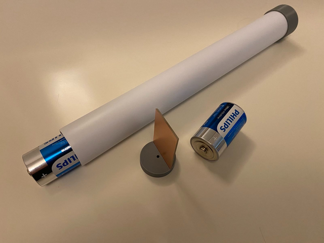
Either i will fit the TX inside the pipe, or build a small head on it for more room. The pipe is Polypropylene plastic, its hard to glue and paint, but cheap and easy to work with. I looked for PVC piping, but couldnt find any in the same diameter. Most of the parts will halfto be press-fitt. I plan to have a floating collar at 80% of the length, and a short whip antenna.

8
The RF Workbench / Re: Hellschreiber beacon - with some oomph!
« on: February 27, 2022, 1810 UTC »
I gave the LULU rf a try, the square wave output from the 74HC240 worked very well, but the output was behaving the same way as before. Output slowly rising for 1-2s and after that it looked like a mess on the oscilloscope. This was the same problem i had with my E class experiments last time.

Perhaps its my 50v ceramic capacitors that doesnt hold upp?

9
The RF Workbench / Re: Hellschreiber beacon - with some oomph!
« on: February 27, 2022, 0751 UTC »
I got rid of the Arduino Micro and got a Attiny45 to do the same job, programmed it with the Tiny AVR Programmer(using Arduino language).

I assume that this is for the outgoing message, correct?

Yes, the Attiny45 carries the code for keying the transmitter and sending the Hellschreiber message. The Attiny works well, despite beeing in close proximity with the 10W transmitter.

10
The RF Workbench / Re: Hellschreiber beacon - with some oomph!
« on: February 26, 2022, 1058 UTC »
I got rid of the Arduino Micro and got a Attiny45 to do the same job, programmed it with the Tiny AVR Programmer(using Arduino language). It lowered the standby current from 40mA to 12mA.

The Attiny45-10pu draws 2,4mA at 5v, probably the oscillator that has a standby current of 10mA.

11
The RF Workbench / Re: Variable frequency oscillator design for HF
« on: February 24, 2022, 1658 UTC »
Looks interesting, i will think about it!

I tested a few crystals i got on line, but they didnt work. Some of them(the one on the right) worked very well, but the one on the left didnt work at all, both the same frequency though. Is there any difference between them that is important(besides the size)?


12
The RF Workbench / Variable frequency oscillator design for HF
« on: February 23, 2022, 1747 UTC »
I have only used crystal oscillators for my builds, but crystals can be hard to find that match the frequency you want to transmitt on. Is there any good and simple VFO altnernatives for HF using a colpitts oscillator for example?

I am looking for something like the lower example in this image, from the ARRL handbook. Is this something i should go for, or is there better and prooven designs?


13
The RF Workbench / Re: Hellschreiber beacon - with some oomph!
« on: February 23, 2022, 1736 UTC »
Congrats! Are you going to put this beacon on the air 24/7 ?

I am thinking bout the applicaitons of this beacon, i will keep you posted  :)

14
The RF Workbench / Re: Hellschreiber beacon - with some oomph!
« on: February 21, 2022, 1707 UTC »
Today i started up the beacon for a test drive, and it worked nicely! I got a clear signal from a web SDR almost 700km away, only using a random wire antenna. I tested it with 10W RF output on 40m(14v supply), TX once a minute, but no issues with temperature. The Arduino controller is mounted on its belly, and i printed out some nice feet for it.

This build was interesting, and i learned a lot about how amplifiers work, and what powers to expect. I also got used to keeping the legs on the components short, and planing the layout better. Thanx for the help and tips i got during the build!

15
The RF Workbench / Re: Hellschreiber beacon - with some oomph!
« on: February 19, 2022, 1615 UTC »
Finally i have completed the smaller circuit, and tested it. I lost a bit off efficiency compared to the "test circuit"(2-3% less), but the output power is very nice. At 13,8v i get allmost 10W of output power after the LP-filter. The amplifier maxed out at 21 watt at 24v  :)

Edit: I managed to increase efficiency to just above 50% by adjusting the bias

Pages: [1] 2