We seek to understand and document all radio transmissions, legal and otherwise, as part of the radio listening hobby. We do not encourage any radio operations contrary to regulations. Always consult with the appropriate authorities if you have questions concerning what is permissible in your locale.

Show Posts

This section allows you to view all posts made by this member. Note that you can only see posts made in areas you currently have access to.


Messages - OgreVorbis

Pages: 1 2 3 4 [5] 6 7 8 9 10
61
The RF Workbench / Re: Making a cheap eBay RF Power Amp Sorta Work
« on: October 06, 2019, 2037 UTC »
That too :)

I am really curious about Greece though. Do they not have any radio laws there? There are so many pirates.

62
The RF Workbench / Re: Class D output match
« on: October 06, 2019, 1841 UTC »
That's interesting. I didn't think you could do CQUAM on a PWM type system. If you don't mind, maybe you could explain it?
There is the Polar Explorer which is able to do class E with SSB.

On the original topic:
I replaced the balun with a coaxial wound one. I found a 1% decrease in efficiency (more or less the same).
I will not give up. I have now sent for revision 4 of my PCB. If this one doesn't work, then I have no clue. The waves were a little rounded on the current one, but this new one has only straight buses and the crystal is hooked up directly.

63
The RF Workbench / Re: Making a cheap eBay RF Power Amp Sorta Work
« on: October 06, 2019, 1831 UTC »
I'd recommend to always go with Greek gear for MW and HF. There's something about Greece that they seem to be obesesed with these frequencies. There is so much stuff available that's better than the Chinese. They even make custom Class D and E.

Here is a good amp from a vendor I've used for a while:
https://www.ebay.com/itm/RF-POWER-LINEAR-AMPLIFIER-AM-MW-HF-HAM-RADIO/323931112378

It might need a pre-amp because I don't know what you're driving with.

Even if you don't need it, I think others might find this guys wares interesting :)
https://www.ebay.com/sch/kleop313/m.html?_nkw=&_armrs=1&_ipg=&_from=

64
The RF Workbench / Re: Stretchyman 40w GaN TX is sick
« on: October 06, 2019, 0927 UTC »
I'll bet the problem is that one of the NCPs is fried.

My newer transmitter uses those NCPs and I fried a lot of them during the testing process. Yes, it is best to apply the low level voltage first and then the HT after.

But Stretchy knows what he's doing and probably has good symmetry and square waves.

I fried so many of those NCPs when I was designing mine. Just a tiny bit off in symmetry or a slightly rounded wave will make those things bake themselves really fast.

I doubt there is a problem with Stretchy's transmitter as he's been doing this a long time. I just don't like those NCPs very much, they're not any better than the 614s and they can't dissipate heat, so if there is a small problem, you're screwed. Maybe it's better in the long run though because it won't allow you to be sloppy. Even in optimum conditions, you can't apply more than 15V to them.

65
If anyone's curious, I eventually went with a AMM-SD1: http://www.radioassociates.com/

This site showed up several times after my search queries, but I ignored it because the name "Radio Engineering Associates" sounds like some type of law firm.
It works well and the price is right.

66
This could very well become a community project.  See related video here https://youtu.be/EwMDEjv1Hfc  I have built a DDS based VFO, but need some way to control it once embedded in the bowls of various pieces of equipment.  The basic idea is this; the project listens to an RS232 port for valid commands.  if it receives something like "f=6925<CR>" the VFO output frequency is set to 6925 KHz and echos "f=6925<CR>".  It would also be nice if other commands like "RF ON", "RF OFF" and "f+5", +10, etc could be implemented.

I've looked all over and haven't really found anything like what I need.  The biggest problem seems to be how to get the serial data into a string, and then begin processing it once it detects a carriage return.  if/then/else statements could then be used to carry out the desired functions.

Thanks in advance,

+-RH

Maybe this would help:
https://arduino.stackexchange.com/questions/48333/very-basic-arduino-uno-serial-readstring-operation

67
The RF Workbench / Re: Class D output match
« on: September 04, 2019, 0303 UTC »
See my last post.

I decided to do a little more research. Given my current PCB and my love for simplicity, I am trying to find a way to use only a single balun for matching - nothing else. I am able to get very high efficiencies up to 5.5 MHz, so it just needs a little extra push. I looked at your video more closely, redhat, and now I see that you have a class D tank circuit followed by a row of caps and then your 1:1 balun. My PCB as it is doesn't have space for a row of caps like this. Maybe I could just do the 1:1 and then follow it with a single DC blocking cap?

So I collected some images of different types of balun options.

With my lack of space, I don't think the first one will be very easy and it will require mods to the PCB. The second one isn't bad, but I have doubts that it will work for the frequencies I want. It looks like the last one is the one I should try. I should be able to do it with my current binoculars and without mods to the PCB. What do you guys think?


68
The RF Workbench / Re: Class D output match
« on: September 03, 2019, 2242 UTC »
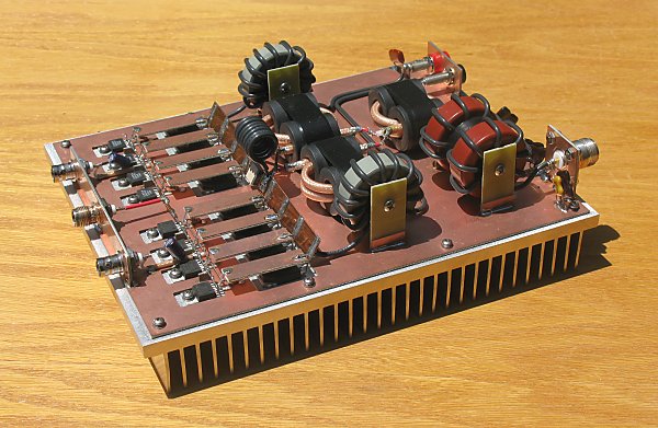
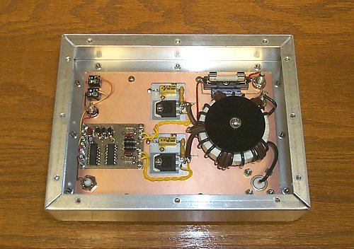
First off, what turns ratio are you needing? Everything I build is 1:1 ratio to keep modulator current levels in sane territory.  I also recently changed the output topology in my transmitter to a coaxial wound binocular type core.  It does get warm at 750 watts carrier, but not hot.  I needed an isolated output in the PA stages to facilitate line derived B+ in the following generations of the transmitter.

FWIW, binocular type output transformers are the standard in solid state PA's from DC to 200 MHz.

+-RH

I think 1:1 is probably fine. It looks like you have the output balun as your only matching. I don't know if that's true or not. I'm not an electrical engineer so I don't understand the "isolated output line derived B+" part.

I see some amplifiers that do the matching with one balun as you do, but I've seen others (especially VHF amps) that use three baluns. One for each side of the amp and then one final on the output. Is there an advantage to this?

Really all I am trying to do is get my efficiency up above 5 MHz. Everything on my PCB has been optimized (no long traces, plenty of caps, good groundplane, good waveforms). I've narrowed the problem to the output match and I think it is the fact that I'm using wire on my output balun instead of coax. I'll try what you did first, redhat, with the coax because that shouldn't be hard. Then Ill try a T200 if it still doesn't work.

69
The RF Workbench / Re: Class D output match
« on: September 03, 2019, 1429 UTC »
I didn't like the binoculars either and used T200-2s, one either side.

So you want to match the output?

Couple of ways....

Use a 1:1 transformer and then conjugate match the O/P (series L,  parallel C). Turns wise, not sure on either but use some scrap wire and experiment, start with 5T on the tran and series L with 1nF C.

Other method is simpler but not as 'adjustable'.

Simply work out your O/P Z, R=V/I, this will be lower than 50R, divide one by the other and take square root to give turns ratio. Standard stuff.

So, say, amp takes 10A@50V=5R.

50/5=10. Square root of 10 is 3 and a bit so use 3:1.

Ok

Str.

OK, thanks! The thing I am confused about is physically how do I wrap the wire on the core? This may seem obvious, but it is not clear to me. Should it be like how I drew in the image or is it incorrect? I don't have space to use two separate cores, but I will use T200A which is a thicker model of the one you mention.

I tried to understand based on this image, but it is not clear:

70
The RF Workbench / Class D output match
« on: September 02, 2019, 2050 UTC »
Hello Stretchy and Redhat, I'm back.

I am going to change the output match on my transmitter to T200-2 or T200A-2 because the binocular thing is not working very well.
I am not sure how to do the windings. How many turns? Maybe either of you have a photo of how you wrapped it.
If I am doing class D, I shouldn't need any other components for matching, just the balun?

Is this how it's done?


Thanks  :)

71
For a couple hundred you can get an HP 8901 Modulation Analyzer on Ebay   It has audio output and is good to 1Ghz  will do all that you want and more  Can set display for peak hold as well.   I run the CRL AM 4 Mono system  Great System but can get grungy fast especially with low bit rate MP3  If your handy there is a Texar Eagle on Ebay that will do a good job of processing your sound

tAC

Excellent. That's what I'm looking for, thanks!

Those professional broadcast monitors like the Belar and Innovonics are a bit too expensive even when used.

72
Equipment / Inverted L ground plane
« on: August 28, 2019, 1059 UTC »
If I have an inverted L, is it better to put most of the radials under the horizontal section? Should I just use a normal circular pattern around the antenna and don't emphasize under the horizontal?

Should the radials under the horizontal extend out more (as if the end of the horizontal is the center of the antenna)? This should form a jelly bean type shape.

Aside from that, it there anything you would recommend for an inverted L (not to purchase; ideas)?

73
Hi,

I am in need of an AM broadcast monitor/receiver. It does not necessarily need to be a professional unit you would find in a radio station studio. I just need a high quality AM receiver with flat response up to 10 KHZ. More would be nice, but not necessary.

A real broadcast monitor with % modulation would be nice, but I am only wanting to pay a couple hundred or less.

I am also interested in an AM broadcast processor. I already found something that pretty much fits the bill, but if any of you have any suggestions, I'd be happy to hear them.

74
Equipment / Re: Inverted V yagi aiming up into the sky
« on: July 20, 2019, 0510 UTC »
I was thinking maybe this would be more useful on medium wave.
The optimal height above ground for a dipole is 0.6 wave, but 1/4 wave comes in pretty close.
AM broadcasting has always been hard because of the height required and the high ground losses in my area.
If I made such a yagi or log periodic on MW band, do you think it would be more effective at getting the energy into the ionosphere than just having it at the correct height?

I mean, with a standard dipole isn't a lot of energy just being absorbed into the ground?

75
Equipment / Inverted V yagi aiming up into the sky
« on: July 19, 2019, 0147 UTC »
So I'm curious why I have not seen this type of antenna before. Basically what it would be is 3 or more inverted Vs stacked on top of each other along the length of the mast. I've seen something somewhat similar with inverted Vs, but not aiming upwards. With HF, we want the signal in the ionosphere, so why not aim it up? Why do hams always aim their yagis horizontally?

And when I say aiming up, I want to be clear. I do know that hams mount horizontally and vertically which is not what I'm talking about. I mean the yagi is pointing up into the sky. I figure with a dipole, the radiation angle wouldn't be right, but with an inverted V I think it would. Plus, it is much easier to install.

Pages: 1 2 3 4 [5] 6 7 8 9 10
HFUnderground T-Shirt
by MitchellTimeDesigns