Loop building is an addictive pastime for me, and there always seems to be some new avenue to explore. I will never say that they are the perfect antenna for every user (what antenna is?), but they have served me well.
Here is an image gallery of a few of the Resonant Loops I have built and used. I add electrical characteristics where I have them. Tuning ranges expressed in kHz are typical with the standard loop amp I use, which has back-to-back tuning diodes giving an approximate 10-250pF range. Parasitic capacitance and inductance of the windings measured via the "2 point method".
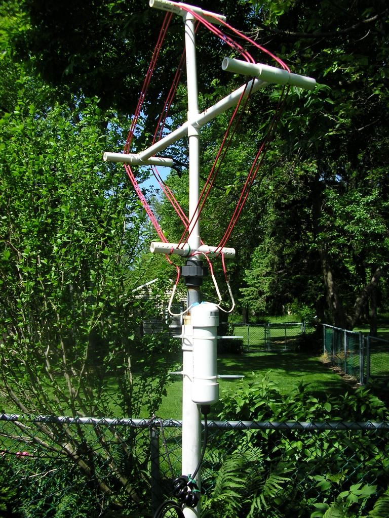 Standard Loop
The loop I use for live DXing and over-nights, and the workhorse antenna for me. A very good performer 60 through 41 meters.
Side = 20"
N = 4 turns
L = 17uH
Cp = 11pF
Wire = 10AWG TEW (27 feet)
Range = 2400-7800kHz
Q ~ 240 @ 6925kHz
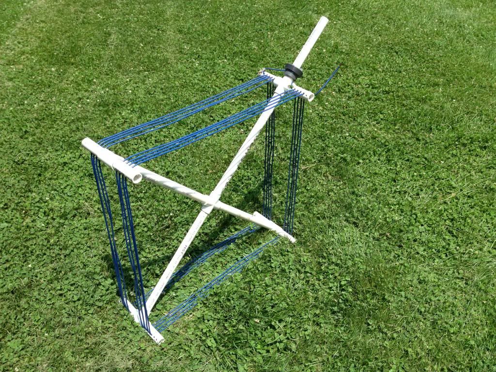 Big Blue Loop
A bigger loop for coverage of MW top end and 90M, and simply the Standard Loop upsized with some extra turns. I need to trim this a bit to get some 75M coverage. Blue wire used for enhanced DX from Oceania.
Side = 25"
N = 8 turns
L = 65uH
Cp = 18pF
Wire = 12AWG TEW (67 feet)
Range = 1200-3700kHz
Q ~ 250 @ 1710kHz
Edit: This loop was used to log a local Part 15 about 30 miles away from me, and I have already posted an image of the SDR reception here:
http://www.hfunderground.com/board/index.php/topic,8377.0.htmlThis was posted with the intent that we would come back to it at some point, and I guess that time is now. With a rough Q of 250 @ 1710kHz, the BW is about 7kHz at that frequency. The response shape is clearly seen in the clear between 1705 and 1720, and attenuation across the WVON 1690 signal is also evident by the color rendering. Note that the loop tuning was not peaked at the resonant peak, but in the lower slope of the response. It was at this tuning that I got the maximum apparent S/N ratio as judged by ear. This is an example of the type of performance I hope can ultimately be wrung out of a loop at 43M, although that will require increasing the current Q of the Standard Loop by a factor of 5.
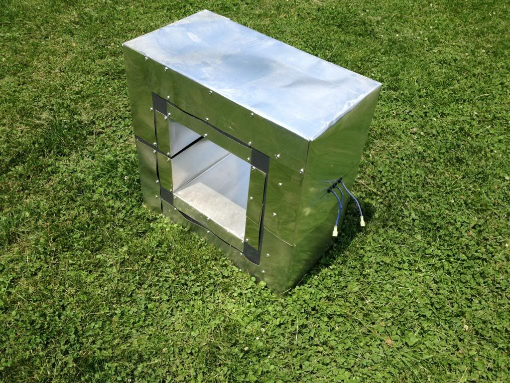
 Shielded Loop Prototype
A standard loop in a shield built from foamboard, aluminum foil, and Scotch tape, and a Standard Loop. My entry into the "Fugly Loop" competition, created out of desperation when the Power Company wouldn't show up to fix a bad pole which was seriously crapping out my noise levels.
Side = 20"
N = 4 turns
L = 16uH
Cp = 11pF
Wire = 10AWG TEW (27 feet)
Range = memory leak
Q ~ 200 @ 6925kHz
What I learned =
1) Shielding a Resonant Loop seems to be effective.
2) The tuning range will be translated up in freq a bit
3) Some degradation of loop Q will be experienced
Audio clip of CFRX 6070 @ 2030UTC in the presence of extreme power pole noise. The initial audio was captured with a standard unshielded loop, and at 42 seconds I switched over to the shielded prototype which was similarly sited.
Link: http://www.mediafire.com/download/4rdk48824h6tnqd/CFRX_6070AM19Oct12_2030z.mp3
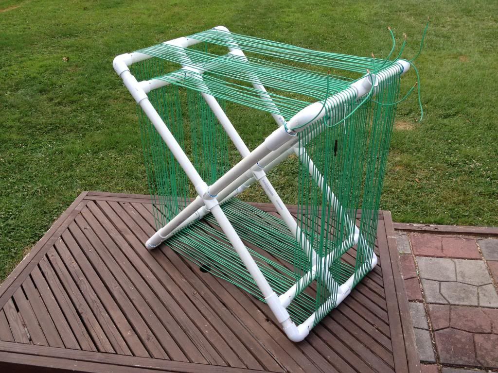
 Shielded Loop Working Model
A slightly smaller standard loop in a shield built from PVC sheet and solids, shielding is aluminum flashing. Since the Power Company has fixed my noisy pole, this is on the back burner. "If you build it, they will come".
Side = 19"
N = 4 turns
L = 15uH
Cp = 11pF
Wire = 10AWG TEW (25 feet)
Range = lost my notes
Q ~ 215 @ 6925kHz
 LF NDB Loop
A Resonant Loop which is exploring some different concepts, and is still being tested. This loop has four independent windings which can be switched into different series/parallel combinations to do band changing. With coils in series, this loop packs about 1250uH into a relatively small volume. This is about the biggest loop which I will be able to swing on my rotor. This loop will be tuned by a primo silver-plated variable capacitor (15-250pF, mil surplus from an ATU) with a built in 100:1 gear ratio via a stepping motor interface.
Side = 32" (outer) and 26" (inner)
N = 24 + 24 turns
L = 1250uH with all coils in series
Cp = 38pF
Wire = 10AWG THHN (464 feet) N.B. I generally do not wind loops from THHN; it kinks, has too much memory, and is almost impossible to tension without frame distortion or breakage. It also generally has a nylon over-jacket which tends to crack when exposed to the elements; this traps moisture which leads to Q degradation. I had a spool lying around and used this while prototyping. This will ultimately be wound with either TEW or Litz, depending.
Range = 265-620kHz with a mechanical variable cap (will be lowered to ~180kHz by remotely switching in
some parallel fixed cap)
Q >= 400 @ 300kHz.(design goal)
What I learned = To get down to 300kHz with the capacitor I wanted to use, a loop inductance of around 1200uH was required. To use the typical winding layout would result in a loop which would have been too large to swing on a rotor in my siting. This loop uses dual windings (4 individual coils) which have a hefty amount of mutual inductance which increases the apparent tuning inductance in a small package. At least, that was my guess, and this appears to have worked.


 Topic: A Gallery of Small Tuned Loops (Read 13801 times)