Common and Precious 5
From HFUnderground
Contents |
Beacon "Common and Precious Nr. 5"
05. of November 2025: New location found
After pondering about options for far longer that intended, the decision for a new location was made. There were some dependencies which needed to be met. A grid connection. At least 100+ meters away from where people live (strong fields is an issue with lots of modern multimedia devices and it might cause issues which lead to authorities to show up). And an option for a larg(er) antenna. I wish I could tell about the structure that will be (ab-)used as an antenna. Likely the most hillarious thing. But I guess sooner or later the site will be demolished as well and after that it can be revealed.
16. of February 2024: permamently offline. See below for details.
Before anyone will ask the obvious: yeah, I went a bit over the top with this project. I kinda wanted to build it and then, when it was done, realised that maybeee... But oh well. It is what it is now. I'm not aiming for more Beacons in this power range. Except maybe one on 2200m. But only because the radition effiency of antennas here is around 0.1-1%.
All Common and Precious Beacons are under re-construction and some in for a re-location. The 2nd generation Beacons will transmit both on CW and RTTY. The new message will carry, besides the usual informative text, also live telemetry Data such as temperature and humidity. An AM2303 sensor is used.
This new Beacon, Nr. 5, is the first to run with the new software and features. If all works fine, the hardware of all other beacons will be upgraded and fitted with the new firmware.
History Backlog
- 22. January 2023: project went on air for the first time. (The Antenna was a 5m vertical with two load coils. One at the base and the second approx 30cm below the capacity hat. It allows for a higher feed point impedance, higher bandwith and also a good radiation of both the inductive and capacitive elemements. The Antenna was installed approx 35m above ground. Matching to 50R+j0 is realised by a simple L/C network. The antenna is a converted lightning rod. The basepoint was isolated from the mounting post by a sleeve made from PVC tube. A blotch of silicone works as a seal and keeps rainwater from seeping into it and causing corrosion together with the RF signal.)
- 24. March 2023: Project off-air. Unexpected demolition works have started. Power has been turned off. A new site was found. Moving the beacon will happen in April.
- 07. August 2023: A new site was found. Setup is in progress. But it's expected that the location has to be changed again within this year. A lot of locations lay dormant for years. But oddly, since the end of the Covid-19 pandemic, a lot sites got demonished (or became marked for demlishing). Turns out a lot of properies got sold during the pandemy and will be used for new objects soon. It becomes more and more tricky to find suitable locations (especially with power available). Additionally, more and more vlogs (Video Blogs) on S1ocial Media about lost places results in an increasing number of people on locations. And with such comes more and more vandalism. Hence, running on Solar might become tricky as well. There's more lost objects available outside my home town, but most require at least a 45-60 minutes drive by car one way. Which I struggle with. Time and ecological wise.
- 08. August 2023: The beacon is operating again.
- 14-16. August 2023: Beacon was down. Copper scavengers cut the cable. Re-Routet a new cable in a place where it's hardly visible.
- Approx end of November 2023 (ongoing): It goes down with the location rapidly. Lots of activities regarding scavengers. They now even go for the thin cables that were left untouched before. Need to re-route a new cable even more hidden. It's winter. Snow and cold. The roof is slippery AF. Fixing the issue will take until the end of the year I guess. But hey, the big scorch mark on the cut cable was satisfying to see. Someone got a nasty suprise.
- 16. of February 2024: permamently offline. I managed to retrieve the whole setup last minute. Demolition work has started and the Antenna (modified lighning rod) was already flat on the roof. Bit of a shame. Right now I'm on the search for new location. Could become hard. Feels like all objects that lay dormant for decades became an interest for new housing projects recently.
Summary and details
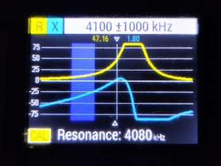
- Frequency: 4.095.400kHz (CW and Mark Frequency). RTTY: 170Hz shift, 50 Baud, 2 Stop-bits 4095.4 kHz 4.0954 MHz
- RF Power: 50W
- Operating since: 22. January 2023
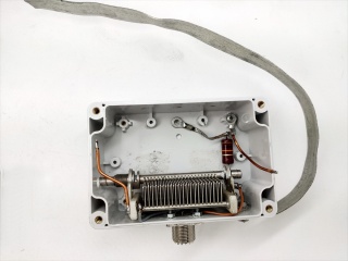
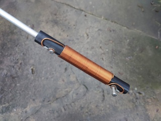
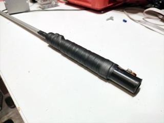
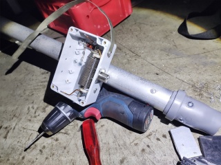
- Antenna: 8m vertical with one load coil at the base together with the match. The Antenna is installed approx 10m above ground. Matching to 50R+j0 is realised by a simple L/C network. The antenna is a converted lightning rod. It sits on a tripod that's held down by concrete weights that also function as an isolator. The former ground connection was cut and connected to the matching box of the antenna instead. The C elemnt is a variable capacitor with additional fixed value styroflex capacitors. The inductor is an air-core type on a PVC tube. An iron power core suitable to handle the load would be too big to fit into the matching box. An additional 10k/2W resistor across the PL socket allows for any static buildup (caused wind / snow / rain or thunderstorm) to pass to ground. The existing grounding grid of the lightning arrester system was used as a counterpoise. (Note: re-tightening and greasing and existing joints may help to remove high contact resistance due to corrosion.)
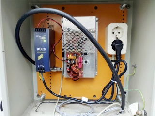
- Power Source: 24V/120W Switch Mode Power Supply. A special industrial type designed for dynamic loads was used.
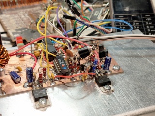
- Oscillator: pulled 4.096kHz X-tal based on a 74LS02 oscillator circuit. Frequency shifting is done by Varicap Diodes (Schottky Diodes were used since they're cheap and exhibit a high junction capacitance).
- Keying: Atmel AVR ATTiny 461 (4kB Flash). An ATTiny26 was used first. First it all looked tight but good. Merging all functions eventually caused the MCU to run out of program memory. It was approx 100 bytes short (a bit more with debugging code still active). A pin compatible type with 4kb was used instead (the hardware had already been build). It also offers room for further features. Fun fact: software entirely done in assembler. Every bit of it. From reading the AM2302 to math and conversion and the CW/RTTY functions. The software is written in librarsies so the code exist as independent blocks that can be use for other/future projects as well. Keeping the code flexible was a key feature in this project.
- Environmental Sensor: AM2303 (in instrument shelter), mounted outside (facing south may cause the temnperature reading during summer to be some degrees above the actual value. But since it's mounted high above the ground it can be assumed that present wind will keep it quite on-spot.)
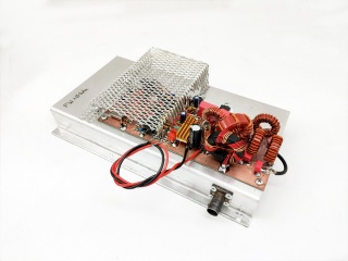
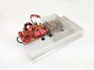
- Power Stage: Class E based on IRF640 FET @ 24V. Driver: MCP1407-E/P. Using a 7-pole (tripple PI) filter. 2nd harmonic supression greater than 33dB.
- System effiency: approx 85%
Some additional notes
- A 9.216.000MHz cryshttps://www.hfunderground.com/wiki/skins/common/images/button_image.pngtal allows to both derivate a 50Hz (20ms IRQ) Baud RTTY signal and also regular RS232 Baud rates from it (for debugging purposes).
- Class E introduces quite some stress to Switch Mode Power Supplies when operating in CW mode. Experience from the recent years has shown that output capacitors will dry up rapidly or become short, oftean leading to a blown up power supply. Use a power supply that can at least provide double the amps drawn by the transmitter. Adding additional high capacity ceramic caps (2-3 x 10µ/50V, usually 1210 footprint) accross electrolytic caps also helps to reduce the stress a great deal. A classic transformer based power supply works also great. Be aware that any 100/120Hz ripple will be audible as AM modulation, thus leading to a higher signal bandwith.
- Suitable (commonly available) FET drivers up to 8..10MHz: MCP1407-E/P, IR2121 or IR2125. Do NOT use the MCPxxE10/E14 series. Despite the datasheet stating good rise- and falltimes, those will become horrible above 1MHz. Discharging of the Gate to the low (off) state will not happen. Also, add some heatsink to any driver IC used. Especially on those with DIL-8 footprint.
Pictures
Hardware
Picture of the current location.
Not available - for obvious reasons.
Former Location - January to March 2023. Old 13 story tall building. Fully demolished by June 2023.
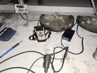
Pictures of the Antenne construction. No pictures of the full antenna available. Which would reveal the location.
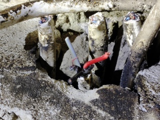
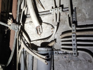
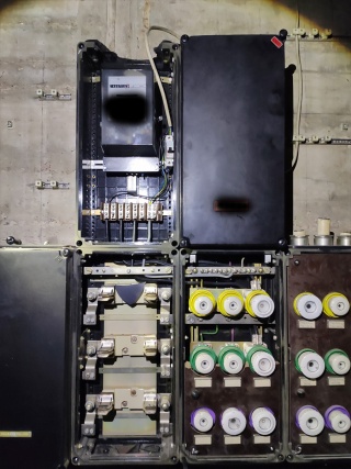
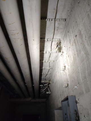
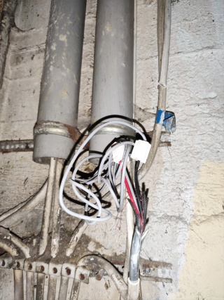
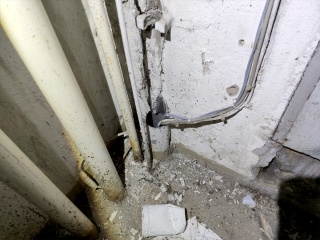
The location was discovered in Winter 2020 shortly before the Covid-19 pandemic. With power available in the elevator engine room on the roof. Sadly, during winter 2020/-21 metal thieves discovered that the building was deserted as well and cut/tore out everything they could.
Power was still available in the heavyily damaged fuse boxes in the basement. Giving up was no option. Wire stubs sticking from the walls were rang out to find a connection from the basement to the staircase through the walls. Single wires we ran through the pipes going through all 13 floors. Took a quite some time. But eventually power was available on the roof again. Sadly again, demolition works suddenly started two months after the installation. Thus, everything had to be removed again. You gain some. You lose some. Sigh.
This site is a participant in the Amazon Services LLC Associates Program, an affiliate advertising program designed to provide a means for sites to earn advertising fees by advertising and linking to Amazon.com. Some links may be affiliate links. We may get paid if you buy something or take an action after clicking one of these.
