Common and Precious 3
From HFUnderground
| Line 26: | Line 26: | ||
| + | == History == | ||
| + | |||
| + | {| width="100%" border="1" cellspacing="0" cellpadding="2" align="left" style="border: #969696; border-collapse: collapse; margin: 50px;" | ||
| + | |- | ||
| + | ! Date !! Issue | ||
| + | |- | ||
| + | | May 2015 || Project kick-off. Evaluating the setup and loacation. | ||
| + | |- | ||
| + | | June 2016 || First prototype of a 500mW version. | ||
| + | |- | ||
| + | | September 2016 || First prototype of a 7W version. | ||
| + | |- | ||
| + | | October 2016 || Clean and stable version of the 7W prototype. | ||
| + | |- | ||
| + | | June 2017 || Antenna construction and setup. Deployment and begin of operation. | ||
| + | |- | ||
| + | | August 2017 || Operation interrupted for about two weeks due to power loss inflicted by rats s gnawing through the mains wires. | ||
| + | |- | ||
| + | | September 2017 || Operation interrupted for about three weeks due to massive antenna damage inflicted by a heavy storm. | ||
| + | |- | ||
| + | |} | ||
| + | |||
| + | <br /><br /> | ||
== Circuit Notes == | == Circuit Notes == | ||
Revision as of 08:58, 24 November 2017
Contents |
Beacon "Common and Precious Nr. 3"
Preliminary documentation
Summary
- Operating since: Sunday, 18. of June 2017
- Power: 7W
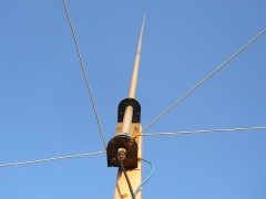
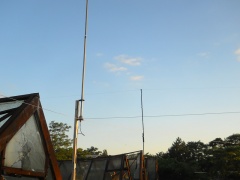
- Antenna: 5/8λ Vertical (modified CB antenna) on a roof, approx 10m above the ground (1,5m above the roof).
- System: Pulled 13.256kHz X-Tal with doubler stage. Uses 3x 2N3904 for oscillator, doubler and buffer. Uses 2N2866 for Driver and 2SC2078 in the PA.
- Keying: Atmel AVR ATTiny25
- Uses two 7 pole (triple PI) filter for harmonics supression.
- System effiency is approx 70%
- Record: 1.094km to Chester, Cheshire, UK (WebSDR, 19. of June 2017)
History
| Date | Issue |
|---|---|
| May 2015 | Project kick-off. Evaluating the setup and loacation. |
| June 2016 | First prototype of a 500mW version. |
| September 2016 | First prototype of a 7W version. |
| October 2016 | Clean and stable version of the 7W prototype. |
| June 2017 | Antenna construction and setup. Deployment and begin of operation. |
| August 2017 | Operation interrupted for about two weeks due to power loss inflicted by rats s gnawing through the mains wires. |
| September 2017 | Operation interrupted for about three weeks due to massive antenna damage inflicted by a heavy storm. |
Circuit Notes
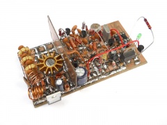
The circuit is done the classic way in full Transistor (all 2N3904) topology. A standard (series) pulled crystall oscillator circuit provides the source signal. It's followed by a buffer stage that has a parallel resonant tank circuit in it's collector path. The tank circuit is tuned to twice the driving frequency. The doubled signal needs some addional filtering. The amplitide of each added sine swing is weaker than the swing that goes with the fundamental frequency. Therefore, the imbalanced singal is feed to a resonant filter stage existing of three series resonant tanks which happen to be coupled with a small capcitance. The Signal at it's output is verry smooth and shows a steady amplitude. This, now clean, signal is amplified once more before feed to the PA driver stage. Impedance matching between the last amplifier stage and the PA driver Transistor is realised with a small transformer (binocular ferrite core). The driver stage uses a 2N3866 with heatsink in class B mode. It delivers approx 1,5W. The final driver stage operates in class C mode and uses a 2SC2078 RF power Transistor (which was designed for use in 11m Band devices like CB radios). Therefore, it works well here and provides approx 8W RF when running at 14V.
A 7 Pole (triple) PI filter ensures harmonics supression that meets the official requirements. Mind: just because you do not-so-legal stuff doesn't mean you need to be lazy and annoy people with harmonics. Be nice and thoughtful. Try not to bug people. Choose your frequency with care and make sure your signal is all clean.
A 7805 fixed voltage regulator provides +5V DC to the Atmel AVR ATTiny25 which generates the morse signal. Keying takes place in the last amplifier stage that drives the 2N3866. The 2N3904 is keyed by using a PNP Transistor (BC557) in it's collector path. Turning on and off the +12VDC and therefore the RF that drives the PA.
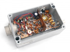
Two LEDs (power = green, key = orange) provide information about the status. The whole board is fit into an old weather proof aluminium chassis. The 2SC2078 is mounted (insulated) to the chassis, providing cooling.
Antenna Notes
All other Common and Precious Beacons operate with 1/2λ dipoles. Given that the site (roof) offers enough space, it was the best decision. Other antenna types easily become tricky to mount or don't have a good efficiency. Staying undercover is also a point here.
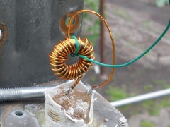
An old CB antenna was choosen for this project. It sat in the basement for almost 15 years. Primary because it was already pretty weather worn and corroded. But it was still enough for such a project. The foot (with its socket) got torn apart. After some experiements a new impedance matching curcuit was installed in it's base. It's an inductor on a ferrite core that fulfills two requirements: providing an inductive reactance (which compensates the capacitive inductance the antenna inhibits) and providing impedance matching (approx 30R to 50R).
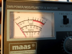
In addition, long ground radial were added. Those are made of simple insulated flexible wire. Four radials, approx 5m each. The SWR is approx 1:1.05, which is excellent.
Project Notes
There's only one way to describe this project: "Oops, this escalated quick...". The basic wish was to build a classic full transistor Transmitter that uses frequency multiplication like it was done in the old days. So far so good. But the project soon escallated when it comes to output power. The project was designed to deliver 500mW, with the intention to operate it with a solar module and Battery pack. That's reasonable for a project in the 11m Band. DXin on this band is only possible during daytime (plus approx one hour before and after sunset). So there's no use in operateing at night. In the end it wasn't 500mW but approx 8W. Why? Well, tinkerer's disease struck. In particular: "Hmm, let's see how far I can get with standard parts and reasonable efforts". Well. you know the outcome now. :)
Project Pictures
This site is a participant in the Amazon Services LLC Associates Program, an affiliate advertising program designed to provide a means for sites to earn advertising fees by advertising and linking to Amazon.com. Some links may be affiliate links. We may get paid if you buy something or take an action after clicking one of these.
