Common and Precious 4
From HFUnderground
Contents |
Beacon "Common and Precious Nr. 4"
Summary
- Operating since: Saturday, 14. of June 2018
- Frequency: 6.395,500kHz 6395.5 kHz 6.395.5 MHz
- RF Power: 2W
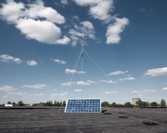
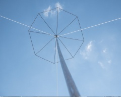
- Antenna: short Vertical (with top capacity) and load coil located 2/3 up the antenna. Installed approx 8m above the ground. 12 radials provide a counterpoise (groundplane). Total height: approx 3m.
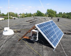
- Power Source: 100W Solar module (20 years old, ~60W effective power) with 12V/7.2Ah Battery backup for night operation. Shuts off at low charge state to prevent deep discharge.
- Current: Idle: ~35mA, Key-down: ~360mA
- System: pulled 6.400kHz X-Tal. Uses 3x 2N3904 for oscillator, buffer and driver and 1x 2N3053 in the PA.
- Keying: Atmel AVR ATTiny25.
- Uses two 7 pole (triple PI) filter for harmonics supression.
- System effiency is approx 48%
- Record: 15. of June, WebSDR in Twende (460km)
History
| Date | Issue |
|---|---|
| 14. June 2017 | Project deployed (with dasher firmware) |
Circuit Notes
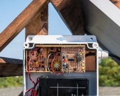
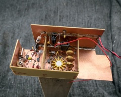
The circuit is done in full Transistor topology (all, except PA, 2N3904). A standard (series) pulled crystal oscillator circuit provides the source signal. It's followed by a class A buffer- and amplifier-stage that feeds the class C PA-driver. Impedance matching between the PA driver and PA itself is realized with a small transformer (FT43 material). Same goes for matching the PA output impedance to the low-pass Filter. The PA uses a 2N3053 Transistor and delivers 3W from 14V. Limiting the power to 2W takes place in the PA driver by limiting the amplification with an emitter resistor.
A 7 Pole (triple) PI filter ensures harmonics suppression that meets the official requirements. Mind: just because you do not-so-legal stuff doesn't mean you need to be lazy and annoy people with harmonics. Be nice and thoughtful. Try not to bug people. Choose your frequency with care and make sure your signal is all clean.
A Z-Diode and NPN Transistor based linear voltage regulator provides +5V DC to the Atmel AVR ATTiny25 which generates the morse signal. An integrated 7805 voltage regulator was not used due to its own (high) power consumption. Keying takes place in the PA driver stage. The 2N3904 in the driver stage is keyed by using a PNP Transistor (BC557) in its collector path. Turning on and off the +12VDC Bus and therefore the RF that drives the PA.
The ATTINY25 provides ADC channels. One is used to sample the Battery voltage. A hysteresis is programmed to make sure the battery charge has reached at least 70% before operation is resumed. Turn-off at 11,0V. Turn-on at 12,5V
Two LEDs (power OK = green, key down = yellow) provide information about the status. The whole board is fit into an old weather-proof PVC chassis. The RF-Module is partly shielded by using bare, copper laminated PCB board.
Antenna Notes
Though the operator experienced excellent results with 1/2λ Dipoles on the lower bands he always wanted to go with a Vertical. The issue with Dipoles is, that they require at least two support poles and guywires to add additional support for the (end-) poles. Not every location might allow the installation of such - for a lot of possible reasons. Vertical antennas come with a somewhat bad reputation for the S/W bands. Primary of three opinions: even a 1/4λ can be pretty high and complicated to erect and support. An (extremely) shortened version (with a load coil) has a bad efficiency. And that they require a big counterpoise (groundplane).
First: true, but every antenna for the S/W bands is bulky. No argument here. Second: the efficiency is lower than that of a un-shortened 1/4λ. But when designed properly (refers to reading literature) not much. Third: both, shortened and un-shortened require an adequate groundplane. When being in the open (i.e. field), lying out some long wires shouldn't be much of an issue.
Anyway. The operator felt for gaining some more practical impressions to compare a 1/2λ Dipole against a shortened 1/4λ Vertical. The base is fed through a small inductor, which allows fine-tuning of the antenna into resonance. The lower part of the beam radiates the magnetic part of the field and the upper part the capacitive while the top capacity provides additional capacity at the end to allow the strong capacitive part to be radiated to the vertical element.
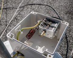
An LC network at the feedpoint provides impedance matching from ~18R to 50R. A SWR of 1:1.08 was obtained.
Project Notes
A fun fact: this concept was the concept designed for Common and Precious I. But it never left the concept phase which was due to two facts: First, even a 200W PV module might not provide enough energy in the winter months for a 24/7 operation. Second, the operator had no experiences regarding vandalism on the location from where the beacons operate. Therefore, he worried about a fast initial loss off a great investment. As time went on and damage was minimal he started to ponder solar based operation again. In addition he found a cheap source for old, second hand and/or partly damaged PV modules which makes a loss less painful money-wise. Now he’s ready to gain some practical experiences regarding the level of PV power required for operation during the winter months.
The solar Module is 20 years old and pretty beautiful (to the operator at least). The operator loves the cell design and the polycrystalline pattern of the cells along with the BUS-finger design. It makes him think of the first PV module he owned as a youngster. It still delivers approx 60W (70W is normal for a 100W module since perfect condition can only be achieved in a laboratory). It’s 24V type that got re-wired into 12V systems in parallel (72 cells module). The module might be replaces by a 170W type to provide more energy during winter and therefore less downtime due to battery protection kicking in.
The frequency close to Common and Precious 3 was chosen on purpose. Even with the difference in RF power level (25W VS 2W) it allows a good comparison of the two setups.
The beacon started operation with a software that only send 1Hz dashes. The operator decided to redo his Text-2-Morse routines and wasn't able to finish the software in time the schedule installation date. Oh-well, changing an IC can always be done later.
Project Pictures
This site is a participant in the Amazon Services LLC Associates Program, an affiliate advertising program designed to provide a means for sites to earn advertising fees by advertising and linking to Amazon.com. Some links may be affiliate links. We may get paid if you buy something or take an action after clicking one of these.
