Thanks for the advice.
I made my first pcb ever and it turned out really great. I didnt use photo transfer, I did it the cheapest way I could with what I had. Which was sharpie marker drawn traces and chloride. PCB turned out perfect! I was pretty surprised as I was expecting a lot of pinholes or for the sharpie to give out and let the copper get etched, but even the fine writing turned out wonderful.
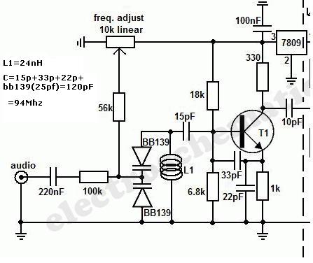
Now I'm having some issues. Here's what I built. This is a cropped version of the original schematic, since I only built the VCO I'm posting this for simplification. Original is here,
http://projectsforece.blogspot.mx/2012/01/long-range-fm-transmitter.html
I built this VCO with a few differences.
The first thin would be that I didnt use the varicaps indicated as those seem impossible to find. Instead I used what I found inside an old wireless phone, I felt blessed to even find that.
I replaced them with two MV2105 varactors. See their data sheet here.
http://www.datasheetarchive.com/dlmain/Datasheets-16/DSA-315502.pdfIt's very hard to find info on the original varicaps used on this vco but the best info I could find on them seems to indicate that it's a 4-45pf device. Meaning in total this would be 8-90pf.
I dont know why this image says the oil is 24nh, the original schematic says 5 turns on 4mm former using 0.6mm wire. I plugged in the L1 coil data into this calculator
http://deepfriedneon.com/tesla_f_calchelix.htmland it tells me it's a .082uH coil. Using the original varicap capacitence this calculatorr
http://www.deephaven.co.uk/lc.html tells me that it has a range of 58.58-196.5mhz
Using the same information and calculator I get that using my varicaps with up to 9v reverse current would go roughly 12pf-30pf (24-60pf in total) and I should get a range of 71.7-113.4mhz which is actually closer to the FM band than with the other varicaps.
The other replacement that I did was probably the more damaging one as instead of using BF199 I ended up using C930 out of an old FM tuner front end. Datasheet here,
http://www.paco-electronics.com/pdf/2SC930.pdfSo the project is built and read, no other values where substituted at all and the thing will not work. I kept the traces as short as possible and I checked for any shorts or mistakes and I cant find any. Could this have to do with my transistor substitution? I cant imagine this having to do with my varicap substitution as the LC calculations say it's fine, if not better.
Any help?
Greatly appreciate any help.
Thanks.


