We seek to understand and document all radio transmissions, legal and otherwise, as part of the radio listening hobby. We do not encourage any radio operations contrary to regulations. Always consult with the appropriate authorities if you have questions concerning what is permissible in your locale.

Show Posts

This section allows you to view all posts made by this member. Note that you can only see posts made in areas you currently have access to.


Messages - Solderon

Pages: [1]
1
Equipment / Re: Construction of Shortwave beacon
« on: July 26, 2021, 1308 UTC »
The beacon is now upp and running again, i rebuilt the power part to use an external source(12v battery and solar panel). The beacon transmitts "SMX 1W BEACON 12V 20C". The voltage and temperature(inside enclosure) is meassured in steps of 1v and 5 degrees c. I will place the TX in the garden for a few days to see how it behaves in the wild.


2
Equipment / Re: Construction of Shortwave beacon
« on: July 25, 2021, 0736 UTC »
The beacon has been running over night, and have had no issues, it handles the temperature well. I redesigned the enclosure to fit better with an external power source, it will be printed during the day.

I also experimented some with the EEPROM(persistant memory) on the arduino, so that i can have it save the number of transmissions and not loose the data even if the voltage becomes too low during the night.


Edit: The beacon is now off line, i am migrating it to the new enclosure  :)

3
Equipment / Re: Construction of Shortwave beacon
« on: July 24, 2021, 1218 UTC »
I run into some problems with the power supply, the new Arduino Micro(and probably the voltage DC-DC regulator) draws 75mA during standby, enough to damage the Lipo batterys during the night. The 18650 batterys looked like a sleek solution to use instead of led-acid or NiMh, but they complicate things a bit, especially since they also are prone to damage due to over loading/discharging. I will half to re-think the power sollution.

I got the transmitter up and running, transmitting at 7028,2kHz every 5 minutes, "SMX 1W BEACON V" followed by a tone that is as long in seconds as the supply voltage, per cell. 4.2 seconds = 4.2volts. The TX will be online a few days to test it out.

4
Equipment / Re: Construction of Shortwave beacon
« on: July 23, 2021, 1822 UTC »
Its beacoming a bit cramped in the box, i added a 8v regulator on the underside of the TX-board, it is fed with a DC-DC voltage regulator that supplies it with 10v, from 5-8,5 volts that the 18650 batteries supplies. The DC-DC regulator isnt regulating very good, so i probably need the L7808 regulator, but it would be nice to not have too much heat production in the box.

The TX will transmitt ID, Voltage, if charging is on, temperature, and numer of tx, all in 15wpm CW. Voltage and temperature will probably be done with a pulse, 0-3s = 0-10v.


5
Equipment / Re: Construction of Shortwave beacon
« on: July 23, 2021, 0944 UTC »
Last night i run into some problems with the arduino nano circuits, my computer no longer discovers them as a serial port for some reason. I spent some time trying different tricks with the FTDI drivers, but came to the conclusion that i just as well should order a couple of arduino micro, "orgiginal" arduino and a lot newer than the ones i have.

Two 18650 batterys fit nicely into the box, with the DC-DC stepup regulator. They should be able to give 9v from 5v-8,4v that the two batterys provide. The transmitter draws 300mA when keying, if the duty cycle for CW is 50% and sending the ID, voltage and temperature takes 15 seconds it requires 2250mAseconds. The battery fully loaded contains 2200mAh/7920000 seconds so if transmitting once every 5 minutes that would last something like 10 days with some efficiency losses.

I will try do design a simple charge controller using a relay that just shuts of the power from the solar panel to the battery if the voltage is over 4,2v per cell. If i use a NC relay there is no risk that the arduino dies due to low voltage, and cant close the charging curcit.

Something like the following peudocode should do it

Code: [Select]
IF Voltage >= 4.2v/cell THEN open charging relay
IF Voltage >= 3v/cell THEN TX(ID, Temp, Voltage)
DELAY(300s)


6
Equipment / Re: Construction of Shortwave beacon
« on: July 22, 2021, 1514 UTC »
Today i cleaned up the oscillator and put an IRF510 PA on the circuit. I also made some tests with supply voltage and power output and got a rubber string that fit nicely into the groove against the lid to keep water out.

The PA added some chirp, and made the output look a bit more "jagged" than before. I have looked at some other PA designs that might give a better signal but i will half to wait for more parts.

I think that 1000mW of output power would be a good level, test of supplyvoltage/RF-out and current draw

12v = 2100mW 540mA
10v = 1800mW 420mA
8v = 1000mW 310mA
6v = 560mW  213mA


Edit: The transmitter runs very cool at 1W output, and only draws 12mA when sleeping(not transmitting). There is how ever a problem with the PA in that it chirps a bit, i have a couple of other designs i could test on the next version. When running at higher output, the transmitter changes frequency sometimes, between the beeps, so that they are heard as two different tones in a SSB receiver. 

7
Equipment / Re: Construction of Shortwave beacon
« on: July 21, 2021, 1557 UTC »
Today some more of the components arrived, and i got the oscillator running with a BD139 transistor. The oscillator is taken from the "ten minute transmitter", or an improved version of it i found online.

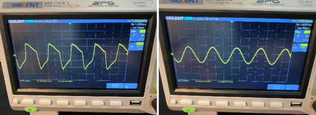
I hooked up the oscillator to a 50ohm dummy load, and checked it with my oscilloscope, and it looked horrible!(left picture). I added a LP-filter and it cleaned up a bit at least. The output is about 500mW after the LP-filter, but its not very frequency stable. The transmitter begins at 7028,3kHz but drops 500Hz after transmitting 5-10 seconds. Perhaps i should add a power amp transistor to unload the oscillator to make it more stable.

The case has been redesigned without the air holes, and some other smaller adjustments. It takes 8 hours to print, but will be ready in the morning.


This is the design i am using, a version of the "ten minute transmitter". 
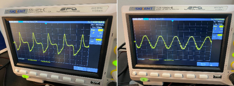
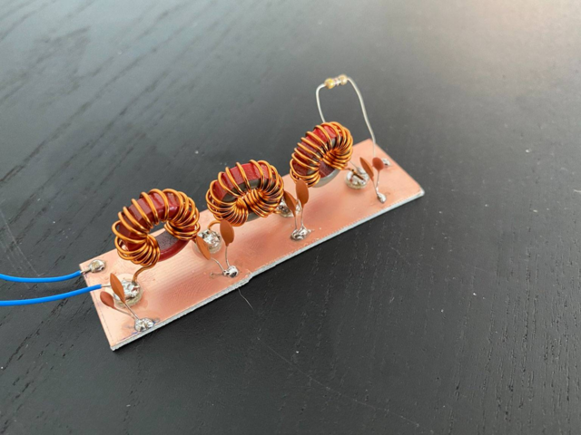
https://hackaday.com/2021/03/11/getting-on-the-air-with-a-10-minute-ish-ham-transmitter/

Edit: I changed the coupling capacitor to the LP-filter, from a 220pF to 940pF, that resolved the chirping and the frequency drift completely, and also made the wave form alot better looking. The RF output got a bit lower as well, and ended up at 300mW. Before and after LP-filter on oscilloscope below.


8
Equipment / Re: Construction of Shortwave beacon
« on: July 20, 2021, 1018 UTC »
To avoid people thinking the transmitter is something else if the find it, i added an explanatory text on the lid "ham radio experiment, radiobeacon 40m". Also found a nice fan grid that fit on the 40mm fan.


9
Equipment / Construction of Shortwave beacon
« on: July 20, 2021, 0745 UTC »
I started a project a couple of days ago, that i would like to share and get some input on. This is a shortwave beacon, that is going to be placed in a forrest and transmitt its callsign and some information about its voltage and temperature on the HF-band, probably somewhere on the 7000-7200kHz.


I have a small crystal oscillator, and a arduino UNO to control it and put it all in a 3d-printed enclosure designed for this project. I also threw in a fan, if temperature would be a problem. I live in Scandinavia, but we do have high temperatures in the summer. The power source will be a small solar panel.

All the parts for the transmitter hasnt arrived yet, but i will keep posting when i make progress.

Pages: [1]
HFUnderground T-Shirt
HFUnderground House Flag
by MitchellTimeDesigns