We seek to understand and document all radio transmissions, legal and otherwise, as part of the radio listening hobby. We do not encourage any radio operations contrary to regulations. Always consult with the appropriate authorities if you have questions concerning what is permissible in your locale.

Author Topic: Simple but effective FM transmitter help VCO  (Read 14248 times)

Offline Tuner

  • Newbie
  • *
  • Posts: 5
    • View Profile
Simple but effective FM transmitter help VCO
« on: December 04, 2013, 1019 UTC »
Hello everyone,

I've been wanting to build a small FM transmitter for a while now but I've always gotten sidetracked and soon forgotten about the projects.  One of the main reasons is availability of parts.  I'd like to build a transmitter using commonly available parts.  Passive components aren't really an issue as much as the active components, mainly transistors or mosfets.  

I'm not looking for a great deal of power I'm mainly just wanting to build a transmitter that goes beyond those DIY type projects that you see everywhere.

Anyone have any good schematics to show me?  I'd really appreciate.

Also thanks for allowing me to be part of this board,  I'm a big radio fan and I'm happy to be among my own kind. Thanks.

« Last Edit: January 07, 2014, 0740 UTC by radiogool »

Offline ff

  • Moderator
  • Sr. Member
  • *****
  • Posts: 443
  • Upstate NY
    • View Profile
Re: Simple but effective FM transmitter help
« Reply #1 on: December 04, 2013, 1537 UTC »
Hi Gool and welcome to the boards.  You'll find a lot of differing opinions about almost anything, including what you asked about.  My opinion, based on my fat-fingered building attempts over the years, is: if you want to do FM - build a kit.  VHF is less forgiving than HF and LF.  Parts placement, orientation, and lead lengths become VERY important.  Kit designers have that all factored into their kits.  And nothing beats having an etched board to stuff your parts into.  There are many kits out there.  And many many differing opinions on which is best.  I only have experience with two, the very expensive and elaborate Panaxis, and this nice little one from Cana Kit:

http://www.canakit.com/hi-fi-stereo-fm-transmitter-kit-ck222b-uk222b-ck222-uk222.html

Whatever you decide to do, best of luck with your project.  Winter is coming and its a great time to do benchwork!
Hailing from the upstate boondocks region of the progressive paradise which once was New York State

Offline redhat

  • DX Legend
  • ******
  • Posts: 1586
  • USA
  • Music is my drug.
    • View Profile
    • Email
Re: Simple but effective FM transmitter help
« Reply #2 on: December 04, 2013, 2046 UTC »
That kit looks like another BA1404 based kit.  If you have the patience to roll your own boards, have a look at these sites;

www.sm0vpo.com Lots of ham based stuff, but a few fm transmitters, and a stereo encoder too.

http://pira.cz/eng/archive.htm similar stuff, more pirate oriented.

Have fun, and if you need help, just yell!

+-RH
Somewhere under the stars...
Airspy HF+, MLA-30/Mini-whip/Chi-Town Loop
Please send QSL's and reception reports to xfmshortwave [at] proton [d0t] me

Offline Tuner

  • Newbie
  • *
  • Posts: 5
    • View Profile
Re: Simple but effective FM transmitter help
« Reply #3 on: December 04, 2013, 2240 UTC »
Thank you guys very much.

I have to stay away from kits because of shipping costs (and the parts of the kits themselves) I'm on a tight budget and my location isnt the best for receiving mail. 

Etching boards is something I'd wish to avoid but I guess if i have to then I have to. :D  I was hoping on possibly just hand etching a board out of copper clad.    Of course there are problems with that, the biggest being sometimes circuits involved etched in coils. 

I was looking at this circuit here.

http://www.electronics-lab.com/projects/rf/001/

But as you can see it includes an etched in coil, L4.  Can I have you guys opinion on trying to build this on a hand etched board and using a wound coil rather than an etched in one?  I dont really know however, how I would go about determining the proper size and turns of the coil.

Another I'm currently looking at is the following,

http://www.circuitstoday.com/2-km-fm-transmitter

Of course a much smaller power output but that's a pretty okay circuit for experimenting.  4 watts like in the other one is a bit more than I initally was looking for anyway, I was thinking more around the area of 1 watt to start up with.


I liked the Harry's Homebrew page

I found this circuit and the related ones rather interesting

http://www.sm0vpo.com/tx/v7_proj.htm

The transistors seem like more of something I could get my hand on.  I'll give it a closer look and I'll write more to you guys about it later on.

Again thank you for the help!


Offline ff

  • Moderator
  • Sr. Member
  • *****
  • Posts: 443
  • Upstate NY
    • View Profile
Re: Simple but effective FM transmitter help
« Reply #4 on: December 05, 2013, 0119 UTC »
I can echo redhat's suggestion about Harry Lythall's site.  He's an expat Brit who was an engineer for Ericsson.  His circuits are quite sound.  I've had good luck with several of his designs...
Hailing from the upstate boondocks region of the progressive paradise which once was New York State

Offline redhat

  • DX Legend
  • ******
  • Posts: 1586
  • USA
  • Music is my drug.
    • View Profile
    • Email
Re: Simple but effective FM transmitter help
« Reply #5 on: December 05, 2013, 0631 UTC »
Yup, its been a cookbook site for me since I started playing on the internet!

+-RH
Somewhere under the stars...
Airspy HF+, MLA-30/Mini-whip/Chi-Town Loop
Please send QSL's and reception reports to xfmshortwave [at] proton [d0t] me

Offline Tuner

  • Newbie
  • *
  • Posts: 5
    • View Profile
Re: Simple but effective FM transmitter help
« Reply #6 on: December 05, 2013, 0755 UTC »
Good news is I just sourced chemicals for etching, opens up many more possibilities!

Yes I enjoyed Harry's site, his V7b with optional synth is really cool and versitile, that's good thinking right there!  Also see a TV transmitter on there too!

Offline redhat

  • DX Legend
  • ******
  • Posts: 1586
  • USA
  • Music is my drug.
    • View Profile
    • Email
Re: Simple but effective FM transmitter help
« Reply #7 on: December 05, 2013, 1553 UTC »
If I may offer some advice on etching boards;  I realize it requires more time and a little more expense, but photo etch processed boards turn out much better than anything I have used before.  My first board was for a veronica 5W VCO transmitter in the late 90's and used Ferric Chloride (Yuck, hate the stuff) and a direct transfer method outlined on Mark Wise's AMN92 site.  It didn't turn out very good, lots of pinholes in the copper, overcut traces, ect.  My next attempt used the toner transfer paper, which has its share of issues as well.  Its difficult to get the toner to stick to the board and not have it flake off during the etch.  The board did turn out better, though.  Finally, the Old Professor got me into the photo transfer process and that's what I've used ever since.  You print out your artwork on transparency film (You have to get this from behind the counter at at Kinko's or something) and hold it against a presensitized board with a thin sheet of glass from a picture frame and expose it to UV for a few minutes, then develop it, and etch with Ammonium Persulfate, which works ten times better than the brown stuff.  Do it right and your boards will look commercial.  I can usually make out the raster lines in the laser printing in my finished boards, something the toner method could never do.  Most of this is under the info section of Harry's site, and also at the MG chemicals site http://www.mgchemicals.com/products/prototyping-and-circuit-repair/.

Also FWIW, most of the professional etch kit components can be made from stuff you buy at a big box mart or equivalent.

Good luck!

+-RH
« Last Edit: December 05, 2013, 1555 UTC by redhat »
Somewhere under the stars...
Airspy HF+, MLA-30/Mini-whip/Chi-Town Loop
Please send QSL's and reception reports to xfmshortwave [at] proton [d0t] me

Offline Tuner

  • Newbie
  • *
  • Posts: 5
    • View Profile
Re: Simple but effective FM transmitter help VCO
« Reply #8 on: January 07, 2014, 0757 UTC »
Thanks for the advice.  

I made my first pcb ever and it turned out really great.  I didnt use photo transfer, I did it the cheapest way I could with what I had.  Which was sharpie marker drawn traces and chloride.  PCB turned out perfect!  I was pretty surprised as I was expecting a lot of pinholes or for the sharpie to give out and let the copper get etched, but even the fine writing turned out wonderful.

Now I'm having some issues.  Here's what I built.  This is a cropped version of the original schematic, since I only built the VCO I'm posting this for simplification.  Original is here, http://projectsforece.blogspot.mx/2012/01/long-range-fm-transmitter.html


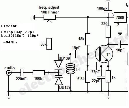
I built this VCO with a few differences.

The first thin would be that I didnt use the varicaps indicated as those seem impossible to find.  Instead I used what I found inside an old wireless phone, I felt blessed to even find that.

I replaced them with two MV2105 varactors.  See their data sheet here.

http://www.datasheetarchive.com/dlmain/Datasheets-16/DSA-315502.pdf

It's very hard to find info on the original varicaps used on this vco but the best info I could find on them seems to indicate that it's a 4-45pf device.  Meaning in total this would be 8-90pf.

I dont know why this image says the oil is 24nh, the original schematic says 5 turns on 4mm former using 0.6mm wire.  I plugged in the L1 coil data into this calculator http://deepfriedneon.com/tesla_f_calchelix.html
and it tells  me it's a .082uH coil.  Using the original varicap capacitence this calculatorr http://www.deephaven.co.uk/lc.html tells me that it has a range of 58.58-196.5mhz

Using the same information and calculator I get that using my varicaps with up to 9v reverse current would go roughly 12pf-30pf (24-60pf in total) and I should get a range of 71.7-113.4mhz which is actually closer to the FM band than with the other varicaps.


The other replacement that I did was probably the more damaging one as instead of using BF199 I ended up using C930 out of an old FM tuner front end. Datasheet here, http://www.paco-electronics.com/pdf/2SC930.pdf

So the project is built and read, no other values where substituted at all and the thing will not work.  I kept the traces as short as possible and I checked for any shorts or mistakes and I cant find any.  Could this have to do with my transistor substitution?  I cant imagine this having to do with my varicap substitution as the LC calculations say it's fine, if not better.

Any help?  

Greatly appreciate any help.
Thanks.
« Last Edit: January 07, 2014, 0835 UTC by radiogool »

Offline ff

  • Moderator
  • Sr. Member
  • *****
  • Posts: 443
  • Upstate NY
    • View Profile
Re: Simple but effective FM transmitter help VCO
« Reply #9 on: January 07, 2014, 1612 UTC »
I'm happy to see you've successfully etched the circuit board Gool.  Me thinks most builders would agree that troubleshooting a non-working project is the hardest part of what we do... or at least the most frustrating.  You've got the right idea - first get the VCO properly working before moving on.  

I shuddered a bit when I read of your substitutions, but I understand.  However, some subs are not as innocuous as swapping a 1K resistor for an 820 ohm.  Finding old varactors IS hard.  I would've subbed it too.  But realize, this can change EVERYTHING with a VCO, or a PLL.  If you have a capacitance meter, I would remove the varactor from the circuit and try to measure the capacitance across it at various voltages to see what it REALLY does - as opposed to what the datasheet says it does.  Sometimes pulls from old equipment have wildly different values than fresh, new components.  If you can get a decent read of what it actually does you can fashion a coil that will resonate properly with it.  If not, I would recommend buying a new varactor pair and custom winding a coil to resonate with them.

The transistor sub looks to me like it should work.  However, I question the wisdom of using an old part in the first place.  2N3904s are just too cheap to be an excuse - and one should work there.  Reusing caps is a VERY bad idea.  If you've done that then any of those units are suspect and could be your problem.  RF projects are much more difficult to get working properly and through the years I've found that the best way to build is to use new parts.  It greatly increases one's chances of successfully completing a project.  I use pulls too, but only for mundane things like audio amps, motor controllers and the like.  When you're playing with RF - use the good stuff.  It's worth the extra cost.  Good luck with your project Gool!
« Last Edit: January 07, 2014, 1621 UTC by ff »
Hailing from the upstate boondocks region of the progressive paradise which once was New York State

Offline jFarley

  • Marconi Class DXer
  • ********
  • Posts: 5922
  • near Chicago
    • View Profile
    • Email
Re: Simple but effective FM transmitter help VCO
« Reply #10 on: January 07, 2014, 2145 UTC »
It's very hard to find info on the original varicaps used on this vco but the best info I could find on them seems to indicate that it's a 4-45pf device.  Meaning in total this would be 8-90pf.

gool;

It's quite possible that the circuit is operating; it just may not be resonating where you think it is.

As drawn, the tank inductance L1 is resonated with a number of elements.  First of all, it is resonated with the variable capacitance diodes which are connected in a back-to-back configuration.  Because of this, the proper range of variable capacitance represented by these diodes is closer to 2 to 23 pF because they are in series, not parallel.

The inductor L1 also has some fixed resonating capacitance represented by the 15, 22, and 33 pF caps.  The equation at the top left seems to treat these as if they were individually parallel elements.  In fact, the inductor L1 sees the approximate series (not parallel) equivalent of these caps, and this is roughly 7 pF. (1/C1 + 1/C2 + 1/C3 = 1/Ceffective)

The inductor L1 thus is tuned by an effective capacitance of 2+7 to 23+7 pF, or 9 to 30 pF +/-.  This will suggest a better value for the value of L1.   For example, at a mid-range total capacitance value of 20 pF, a value of 0.13 uH for L1 will resonate at 100 MHz.  Sounds like you're close, and may need a few more turns on L1.

Hope this helps, and hope I didn't fat-finger the TI-30 too badly!

Joe Farley, Near Chicago
SDR-IQ / R8 / R7
Remote Resonant Loops for HF and LF / ALA 1530
Active 60" Whip / PA0RDT
QSLS appreciated to:    jfarley44@att.net

Offline Tuner

  • Newbie
  • *
  • Posts: 5
    • View Profile
Re: Simple but effective FM transmitter help VCO
« Reply #11 on: January 07, 2014, 2348 UTC »
I found the problem and now the VCO works perfect.  The issue was the 15pf capacitor in series with the tank circuit.  It was the incorrect value, I didnt notice when I put it in that it's actually a 1.5pf as opposed to 15pf.  I just couldnt see the point in there til I got a closer look.  With the new change the VCO is working awesome and sweeps across the band no problem with very good audio quality.

Thanks for the advice guys.  I figured the C930 would be a better choice vs a new 2N3904 or something a long those lines since it's an RF transistor. I suppose the original part called for would maybe have a bit more gain?  The plans say the VCO should do 30 meters roughly on a 70cm wire and this does maybe 7 or 8.  Although granted I'm trying it with a lot obstructions around.  Should try it on a clearer area. 

Not sure if I'll be building the rest of it yet as I need to source some more components that are going to be tricky to get, mainly the cap trimmers.

Thanks again. 
« Last Edit: January 07, 2014, 2354 UTC by radiogool »