616
General Radio Discussion / Re: Using imgur for posting images
« on: December 19, 2022, 2240 UTC »
I post images from imgur without an account.

This section allows you to view all posts made by this member. Note that you can only see posts made in areas you currently have access to.
 ) They don't just hand out the programming info to any schmuck that writes to them asking for it.
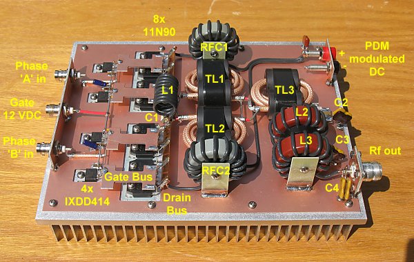
For me one of the appeals of CMCD was the elimination of most of the cumbersome ferrite in the output section. I even started using hardline (0.141") coax as a combination tank resonator and output transformer. No ferrite required!

Marie Osmond wants you guys to know she's still working on that 50 pounds.


Doubt this is still Thunder Chicken due to such low signal strengthRight.
He said he was signing off after one last song, now finished